[email protected]
Well-Known Member
I decided to ship my differential out for chrome. I figured I would try to disassemble it down to the bare case to same some money in the process. To be truthful, I was a little intiminated by the process. There is a lot of talk about special tools and troublesome tasks in the manual.
I can say that I did accomplish teardown without much of an issue. Hopefully assembly goes just as smooth. I am open to any suggestions from folks who have done the process.
If anyone is thinking about tearing into one I can offer up some pointers that I learned in the process. By NO means am I an expert. As noted in the thread title, this is shadetree mechanic style.
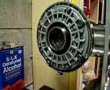
The first thing I did was fab up a plate to hold the differential. Something large and sturdy was needed as there will be a lot of force applied when removing parts.
I placed the plate on the back of the swingarm and traced the hole pattern for the rear differential mounting studs. Once the stud location is marked on the plate you need to find the center point between all 4 stud holes. This is simply done by drawing a X over the 4 holes. I drilled the 4 mounting hole with a 3/8" bit and reamed them slightly. I then grabbed a 2.5" holesaw and drilled a hole in the center of the differential studs. However, a 2.5" hole is not large enough, I had to file the hole slightly larger to allow the pinion bearing retainer to be removed.
Here is what the plate looks like mounted to the differential

Once the differential is mounted you need to work on removing the pinion nut. First step here is to "un-stake" the nut. From the factory, this nut is hit with a punch to lock it in place. This is easily accomplished with a small screwdriver, punch, or awl. Don't drive the tool too deeply or else you could mar the threads behind.
At this point, you would need a special tool from yamaha to hold the gear coupling from rotating while removing the pinion nut. I needed to improvise. I removed the drive assembly (clutch hub) from the rear wheel. Just remove one snap ring and it slides right off the wheel. Insert the assembly into the rear differential. Now, take a STRONG bar (I used a 24" forged cresent wrench) and place it between the drive studs that fit into the wheel dampers and orient it so that the bar will wedge against the vise when you loosen the pinion nut. This will keep the gears from turning when you loosen the pinion nut. Mine was on tighter than hell. I stress using a strong bar because this is what happens when I tried using a piece of sch 40, 1/2" rigid conduit .

The pinion nut comes of counter clockwise. It has normal threads. There is a washer behind the nut, and the gear coupling should now slide right off.
You are now ready to remove the clutch hub and set it aside. You can also remove the center section that houses the ring gear. Loosen the nuts and two bolts in a criss cross fashion. Once these are removed, you need to pry the center section out of the housing. It is a tight fit. Do just a little at a time, working your way around the housing. Once you break it free a little it will come off much easier.
Once the center section is free, remove it. Be ready to soak up some gear oil no matter how well you thought you drained the diff. The plastic shroud will now lift right off the housing.
Now, you will want to remove the pinion bearing retainer. This needs turned CLOCKWISE. It has reverse threads. The retainer has 4 slots in it and again, you should have a special tool for this. I went to the auto parts store and found a 1-5/8" hub socket with 4 prongs that I modified to fit. Modification was just a little filing of the 4 pins to fit the slots of the diff.


The tool worked great and the bearing retainer removed quite easily. It is supposed to be torqued to 80 ft-lbs but mine seemed much looser.
Before removing the pinion gear and bearing you need to remove some other parts for access. There is a guide collar that the axle slides through. It is pressed into the case. I used a bearing/bushing driver to tap it from the case. Install the driver on the outside of the case where the axle nut goes and tap it thru. Next step is to remove the large needle bearing that the center section rides on. I used a large drift to tap it out. Insert the drift from the out side of the case and lightly tap it out. Behind this bearing there is an oil seal. Again, tap it out of the case with a drift.
Now, you are ready to remove the pinion gear. It runs on two bearings. One ball bearing is pressed onto the shaft and there is an oil seal also. This will come out as one assembly. There is a needle bearing in the case that will remain.
To remove the pinion gear I grabbed a thin drift and lightly tapped on the tip of it. The tip is accessible in a small hole in the case where the needle bearing is. Be careful not to get carried away and smack it right out of the case and onto the floor. It does not come out very easily so I don't see this happening.
The needle bearing that the tip of the pinion rides on is the next step. I've heard this one can be tough. I must have got lucky. I borrowed a blind bearing puller from the auto parts store. I grabbed a piece of rubber mat and lined the bore of the differential where the pinion bearing retainer threads are to prevent marring them when I install the puller. The puller is difficult to tighten because it is inside the differential and not much room for a wrench, it is possible though. Be sure that the puller has a good bite on the bearing. One swift hit of the dead blow and it popped out.


Now, the only thing left is the vent. I was unable to remove the vent without damaging it. I tried to work it out easy but the cap snapped right off. Once the cap snapped off, I gripped the body of the vent with vise grips and twisted it right out.

If all went well your housing should be bare and your ready to rebuild it.

I will try to remember to take some better photos of reassembly showing some more detail
I can say that I did accomplish teardown without much of an issue. Hopefully assembly goes just as smooth. I am open to any suggestions from folks who have done the process.
If anyone is thinking about tearing into one I can offer up some pointers that I learned in the process. By NO means am I an expert. As noted in the thread title, this is shadetree mechanic style.
The first thing I did was fab up a plate to hold the differential. Something large and sturdy was needed as there will be a lot of force applied when removing parts.
I placed the plate on the back of the swingarm and traced the hole pattern for the rear differential mounting studs. Once the stud location is marked on the plate you need to find the center point between all 4 stud holes. This is simply done by drawing a X over the 4 holes. I drilled the 4 mounting hole with a 3/8" bit and reamed them slightly. I then grabbed a 2.5" holesaw and drilled a hole in the center of the differential studs. However, a 2.5" hole is not large enough, I had to file the hole slightly larger to allow the pinion bearing retainer to be removed.
Here is what the plate looks like mounted to the differential
Once the differential is mounted you need to work on removing the pinion nut. First step here is to "un-stake" the nut. From the factory, this nut is hit with a punch to lock it in place. This is easily accomplished with a small screwdriver, punch, or awl. Don't drive the tool too deeply or else you could mar the threads behind.
At this point, you would need a special tool from yamaha to hold the gear coupling from rotating while removing the pinion nut. I needed to improvise. I removed the drive assembly (clutch hub) from the rear wheel. Just remove one snap ring and it slides right off the wheel. Insert the assembly into the rear differential. Now, take a STRONG bar (I used a 24" forged cresent wrench) and place it between the drive studs that fit into the wheel dampers and orient it so that the bar will wedge against the vise when you loosen the pinion nut. This will keep the gears from turning when you loosen the pinion nut. Mine was on tighter than hell. I stress using a strong bar because this is what happens when I tried using a piece of sch 40, 1/2" rigid conduit .
The pinion nut comes of counter clockwise. It has normal threads. There is a washer behind the nut, and the gear coupling should now slide right off.
You are now ready to remove the clutch hub and set it aside. You can also remove the center section that houses the ring gear. Loosen the nuts and two bolts in a criss cross fashion. Once these are removed, you need to pry the center section out of the housing. It is a tight fit. Do just a little at a time, working your way around the housing. Once you break it free a little it will come off much easier.
Once the center section is free, remove it. Be ready to soak up some gear oil no matter how well you thought you drained the diff. The plastic shroud will now lift right off the housing.
Now, you will want to remove the pinion bearing retainer. This needs turned CLOCKWISE. It has reverse threads. The retainer has 4 slots in it and again, you should have a special tool for this. I went to the auto parts store and found a 1-5/8" hub socket with 4 prongs that I modified to fit. Modification was just a little filing of the 4 pins to fit the slots of the diff.
The tool worked great and the bearing retainer removed quite easily. It is supposed to be torqued to 80 ft-lbs but mine seemed much looser.
Before removing the pinion gear and bearing you need to remove some other parts for access. There is a guide collar that the axle slides through. It is pressed into the case. I used a bearing/bushing driver to tap it from the case. Install the driver on the outside of the case where the axle nut goes and tap it thru. Next step is to remove the large needle bearing that the center section rides on. I used a large drift to tap it out. Insert the drift from the out side of the case and lightly tap it out. Behind this bearing there is an oil seal. Again, tap it out of the case with a drift.
Now, you are ready to remove the pinion gear. It runs on two bearings. One ball bearing is pressed onto the shaft and there is an oil seal also. This will come out as one assembly. There is a needle bearing in the case that will remain.
To remove the pinion gear I grabbed a thin drift and lightly tapped on the tip of it. The tip is accessible in a small hole in the case where the needle bearing is. Be careful not to get carried away and smack it right out of the case and onto the floor. It does not come out very easily so I don't see this happening.
The needle bearing that the tip of the pinion rides on is the next step. I've heard this one can be tough. I must have got lucky. I borrowed a blind bearing puller from the auto parts store. I grabbed a piece of rubber mat and lined the bore of the differential where the pinion bearing retainer threads are to prevent marring them when I install the puller. The puller is difficult to tighten because it is inside the differential and not much room for a wrench, it is possible though. Be sure that the puller has a good bite on the bearing. One swift hit of the dead blow and it popped out.
Now, the only thing left is the vent. I was unable to remove the vent without damaging it. I tried to work it out easy but the cap snapped right off. Once the cap snapped off, I gripped the body of the vent with vise grips and twisted it right out.
If all went well your housing should be bare and your ready to rebuild it.
I will try to remember to take some better photos of reassembly showing some more detail