


A crack in PCB track is listed as a common cause for VBoost module failure.
I cleaned up the connectors and checked that 12V was reaching the backside of the module connector, it was so the problem is inside.
The plastic case is held together by tabs to and easily sprung apart. The PCB is covered in what appears to be a silicone sealant type coating that was a PITA to remove from the underside, I started on the top but gave up.
I then went over some of the joints with solder and lo and behold it worked ….. but the joy was short lived.
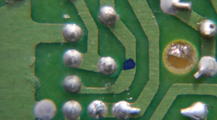
So I plugged the bare board and tapped it and it started to work = conclusion a break in a track or joint that was making contact when the board flexed. Getting out a magnifying glass, I saw one of the joints I hadn't gone over had a fracture all the way round - to the left of the blue dot.
A quick going over with the soldering iron fixed it.
To say I am happy is an understatement.")
I see what's happened, photo is hosted on another site, need to locate the original......
Orange arrow points to the fractured joint, you can see the circular crack.

Orange circle on top of the crack.

I cleaned up the connectors and checked that 12V was reaching the backside of the module connector, it was so the problem is inside.
The plastic case is held together by tabs to and easily sprung apart. The PCB is covered in what appears to be a silicone sealant type coating that was a PITA to remove from the underside, I started on the top but gave up.
I then went over some of the joints with solder and lo and behold it worked ….. but the joy was short lived.
So I plugged the bare board and tapped it and it started to work = conclusion a break in a track or joint that was making contact when the board flexed. Getting out a magnifying glass, I saw one of the joints I hadn't gone over had a fracture all the way round - to the left of the blue dot.
A quick going over with the soldering iron fixed it.
To say I am happy is an understatement.
I see what's happened, photo is hosted on another site, need to locate the original......
Orange arrow points to the fractured joint, you can see the circular crack.
Orange circle on top of the crack.
Last edited:
.jpeg")
.jpeg")
.jpeg")