


WolfMax
Member
This info is intended for people who have at least a basic knowledge of electronics or can understand a schematic to create a circuit.
If you build this, I take no responcibility if after fitting, it fails and frys your wiring. It is for this reason that I'm not offering to make them myself. If this causes concern then you should fit an inline fuse (1A should suffice but 2A is max) to the BRN (Brown) wire between P1 and the circuit.
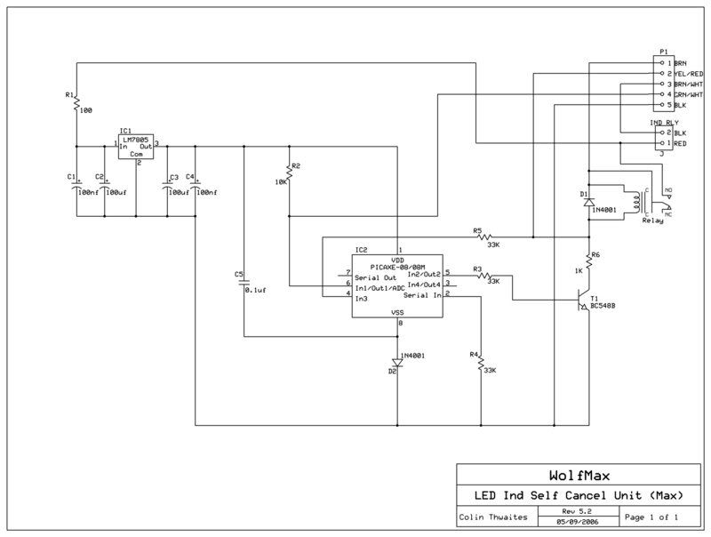
I spent a month developing, testing and finally perfecting, a self cancelling unit for use with my LED indicators and aftermarket Indicator relay (no ballast resistors). The circuit below is for a standard Vmax speedo (untested as I have an Acewell speedo), but it works in the same way as for the Acewell but just needs to count more pulses for the Max (a LOT more).
P1 wires connect to where the standard Max indicator unit connected (Usually removed so an after market 2 Wire relay can be used so LED indicators can work without ballast resistors being employed).
Circuit discription:
The circuit has two main parts. The first is a voltage regulator to convert the 12V from the bike to 5V required by the chip. The second part (the 'Chip') is a small programmable intergrated circuit (PIC) that counts pulses from a switch in the speedo to workout how far and how long the bike has traveled with its indicators on.
The rest of the circuit is for controlling the indicator relay operation. Indicated direction is still controlled by the indicator switch.
The main chip can be obtained from here:
http://www.rev-ed.co.uk/picaxe/
As well as all relevent info on how to setup the programming link and download the free software to program the chip with (in BASIC programming language).
Parts list:
IC1 - LM7805 Maplin Part No. CR14Q
Relay - FRS1 Conrad Part No. 505196-8A
D1, D2 - 1N4001 Maplin Part No. QL73Q
T1 - BC548B (BC549C Maplin Part No. QQ15R)
Resistors are metal film type 0.6W
Capacitors are electrolytic
Basic operating detail: Operate Ind sw (fully). YEL/RED wire goes low (Gnd) switching on relay which powers circuit and Ind. First thing circuit does, switch on transistor to latch relay. Release Ind switch to center pos causes leg 4 to go high (5v approx) program starts to count Time & pulses (GRN/WHT wire). After 15 sec and the requiered no of pulses (542), the chip turns off the transistor releasing the relay turning off both the Ind and the circuit. If the Ind sw direction changes, YEL/RED will go low breifly and cause the program to restart the time & distance counts from 0. If the Ind are manually cancelled, the Ind will go out immediatly however the circuit, will continue to count and will switch itself off at the end but will be reset if Ind are re-applied.
The reason for counting Time and pulses is to account for stopping at junctions and for high speed manouvers. If I just counted time, a stop at a junction may take more than 15 sec and you would have to keep switching the indicators on. If i had counted pulses only, during high speed lane changes, it is concevable that you could cover 100M before leaving the lane and your indicators would go out before you performed the manouver.
The controll program is:
' Program starts when Ind switch is pulled ether side
Main: Symbol Trigger = Pin1 ' Input pin no, not chip leg no
Symbol Reset = Pin3
Symbol Time = 54 ' Equivelent to 15 sec
Symbol Distance = 542 ' number of pulses to count from Speedo switch for approx 100m
Symbol Check = b1
Symbol Timer = w1
Symbol Travel = w2
Let Dirs = %00000101
Let Pins = %00000100
Restart: Let Check = 0
Let Timer = 0
Let Travel = 0
Start: Branch Reset,(Restart) ' Waits for release of Ind switch back to centre
ContAce: If Timer >= Time and Travel >= Distance then IndOff ' Ind off when conditions met
For b0 = 1 to 100
Branch Reset,(Restart) ' Test for Ind switch direction change to reset counters
If Trigger <> 0 then Skip1 ' Test for pulse trigger
Pause 3
Let Check = 1
Branch Trigger, (Repulse, Skip2) ' Test for pulse release
RePulse: Let Check = 0
If Travel >= Distance then Skip2 ' stop pulse over count
Let Travel = Travel + 1
Skip1: Branch Check ,(Skip2, RePulse) ' Check for missed pulse
Skip2: Next
If Timer >= Time then ContAce ' Stop Timer over count
Let Timer = Timer + 1
Goto ContAce
IndOff: Low 2 ' Switch off relay to cancel Ind
End
Note: Any text on a line after a ' is a remark, and is ignored by the program interface.
Text preceeding a : (Skip1: for eg) are branch labels and would nomally have 3 or 4 spaces between the : and the rest of the line to make program reading easier.
Just copy and paste into the programing editor.
The circuit was constructed on strip board and all components except the two wire indicator relay (Motrax) were soldered to it.
Any questions, please ask (It may be a while till I reply as I don't frequent the site often).
This circuit has been on my bike since 2006 without incident. If there is anything I would do different it would be to fill the box the circuit is in with potting compound to prevent vibration breaking any of the componant legs (this hasn't happened yet I might add).
EDIT:
I forgot to add that the little turn signal bulb in the instument pod will need to be ether removed or moddified using diodes to make isolated inputs (see the post by satariel666 below).
Cheers
If you build this, I take no responcibility if after fitting, it fails and frys your wiring. It is for this reason that I'm not offering to make them myself. If this causes concern then you should fit an inline fuse (1A should suffice but 2A is max) to the BRN (Brown) wire between P1 and the circuit.
I spent a month developing, testing and finally perfecting, a self cancelling unit for use with my LED indicators and aftermarket Indicator relay (no ballast resistors). The circuit below is for a standard Vmax speedo (untested as I have an Acewell speedo), but it works in the same way as for the Acewell but just needs to count more pulses for the Max (a LOT more).
P1 wires connect to where the standard Max indicator unit connected (Usually removed so an after market 2 Wire relay can be used so LED indicators can work without ballast resistors being employed).
Circuit discription:
The circuit has two main parts. The first is a voltage regulator to convert the 12V from the bike to 5V required by the chip. The second part (the 'Chip') is a small programmable intergrated circuit (PIC) that counts pulses from a switch in the speedo to workout how far and how long the bike has traveled with its indicators on.
The rest of the circuit is for controlling the indicator relay operation. Indicated direction is still controlled by the indicator switch.
The main chip can be obtained from here:
http://www.rev-ed.co.uk/picaxe/
As well as all relevent info on how to setup the programming link and download the free software to program the chip with (in BASIC programming language).
Parts list:
IC1 - LM7805 Maplin Part No. CR14Q
Relay - FRS1 Conrad Part No. 505196-8A
D1, D2 - 1N4001 Maplin Part No. QL73Q
T1 - BC548B (BC549C Maplin Part No. QQ15R)
Resistors are metal film type 0.6W
Capacitors are electrolytic
Basic operating detail: Operate Ind sw (fully). YEL/RED wire goes low (Gnd) switching on relay which powers circuit and Ind. First thing circuit does, switch on transistor to latch relay. Release Ind switch to center pos causes leg 4 to go high (5v approx) program starts to count Time & pulses (GRN/WHT wire). After 15 sec and the requiered no of pulses (542), the chip turns off the transistor releasing the relay turning off both the Ind and the circuit. If the Ind sw direction changes, YEL/RED will go low breifly and cause the program to restart the time & distance counts from 0. If the Ind are manually cancelled, the Ind will go out immediatly however the circuit, will continue to count and will switch itself off at the end but will be reset if Ind are re-applied.
The reason for counting Time and pulses is to account for stopping at junctions and for high speed manouvers. If I just counted time, a stop at a junction may take more than 15 sec and you would have to keep switching the indicators on. If i had counted pulses only, during high speed lane changes, it is concevable that you could cover 100M before leaving the lane and your indicators would go out before you performed the manouver.
The controll program is:
' Program starts when Ind switch is pulled ether side
Main: Symbol Trigger = Pin1 ' Input pin no, not chip leg no
Symbol Reset = Pin3
Symbol Time = 54 ' Equivelent to 15 sec
Symbol Distance = 542 ' number of pulses to count from Speedo switch for approx 100m
Symbol Check = b1
Symbol Timer = w1
Symbol Travel = w2
Let Dirs = %00000101
Let Pins = %00000100
Restart: Let Check = 0
Let Timer = 0
Let Travel = 0
Start: Branch Reset,(Restart) ' Waits for release of Ind switch back to centre
ContAce: If Timer >= Time and Travel >= Distance then IndOff ' Ind off when conditions met
For b0 = 1 to 100
Branch Reset,(Restart) ' Test for Ind switch direction change to reset counters
If Trigger <> 0 then Skip1 ' Test for pulse trigger
Pause 3
Let Check = 1
Branch Trigger, (Repulse, Skip2) ' Test for pulse release
RePulse: Let Check = 0
If Travel >= Distance then Skip2 ' stop pulse over count
Let Travel = Travel + 1
Skip1: Branch Check ,(Skip2, RePulse) ' Check for missed pulse
Skip2: Next
If Timer >= Time then ContAce ' Stop Timer over count
Let Timer = Timer + 1
Goto ContAce
IndOff: Low 2 ' Switch off relay to cancel Ind
End
Note: Any text on a line after a ' is a remark, and is ignored by the program interface.
Text preceeding a : (Skip1: for eg) are branch labels and would nomally have 3 or 4 spaces between the : and the rest of the line to make program reading easier.
Just copy and paste into the programing editor.
The circuit was constructed on strip board and all components except the two wire indicator relay (Motrax) were soldered to it.
Any questions, please ask (It may be a while till I reply as I don't frequent the site often).
This circuit has been on my bike since 2006 without incident. If there is anything I would do different it would be to fill the box the circuit is in with potting compound to prevent vibration breaking any of the componant legs (this hasn't happened yet I might add).
EDIT:
I forgot to add that the little turn signal bulb in the instument pod will need to be ether removed or moddified using diodes to make isolated inputs (see the post by satariel666 below).
Cheers
Last edited: