speed sensor

VMAX  Forum

Help Support VMAX Forum:

This site may earn a commission from merchant affiliate links, including eBay, Amazon, and others.

bumper

Well-Known Member
Joined
Aug 26, 2011
Messages
172
Reaction score
1
Location
Sioux Falls, SD
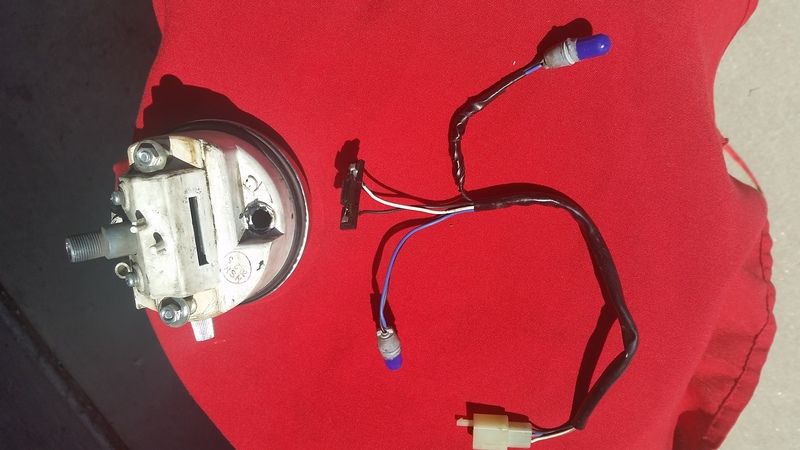
Ok, need to pick a few peoples minds. The speedometer has a speed sensor in it that tells the turn signal relay a distance traveled so it cancels the turn signals. What kind of signal is it sending. A low voltage pulse?

I put one of the cheapy Chinese speedometers on my vmax and now the turn signals don't self cancel because the flasher is not getting the signal from the speedometer any more. It looks like there is about a 10 volt pulse signal and the speedometer plug that is hooked to the sensor. Is that correct? There is also a pulse signal on the Chinese speedometer of about 5 volts. With out plugging in a frying something I wonder if that signal will work with the flasher. Maybe somebody has done this already?
 
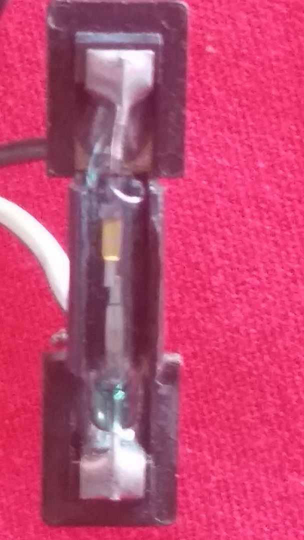
Inside the original speedo there is a reed contact, basically a switch that makes contact when a magnet passes by. The magnet is attached to the flywheel inside the speedo. I am not sure how the 'counting logic' works but since it`s well, let`s say, vintage, it can be tricky to set that up to work with an alternative source.

Also, the flywheel inside the speedo will revolve quite a number of times before the wheel has made one rotation. An aftermarket speedo normally uses a reed contact that you place close to the wheel and picks up the magnet attached to the wheel. This will only give you one pulse per rotation. That might result in the indicator staying on for miles.....

Good luck!
 
The speedometer can be set for 8 pulses per rotation by putting the 8 magnets on the wheel. So I think that part can be worked out. Looking at a wiring diagram I don't see where the we sensor in the speedometer head would pick up the voltage for a signal to send to the canceling relay. Checking the plug there is a voltage pulse as the wheel turns. I am gonna get this sucker to work somehow. Thanks for the reply, I didn't know what was in the head that produced the signal.
 
Interesting work your doing here but, I would just push the button to turn em off instead of worrying about trying to fix it :biglaugh:
 
I know but I am kinda anal when it comes to stuff like this. I like the challenge. And the gas gauge is going to work to....it has an oddball ohm range, but looks like VDO is the answer
 
Not sure if this will help. I have a schematic I redrew several years ago. Much easier to follow than the factory version.

On left side of schematic, near center the speed sensor is shown and its related connector & wire colors.

I also attached a picture showing speed sensor with a red arrow pointing to it.

I have not had the opportunity to verify schematic for accuracy. I only own parts of a VMax, never had a complete one.

Gary
 

Attachments

  • speed sensor.jpg
    speed sensor.jpg
    111.6 KB · Views: 16
  • VMax 85-89 Wiring Diagram Rev A.pdf
    134.2 KB · Views: 10
So in theory the pulse coming from the pickup for the digital speedometer should work if hooked to the connecter on the main harness where the original speedometer sent the pulse to the turn signal canceling relay. Same theory and application. From what I can tell the voltages are slightly different so if the relay is ok with that difference and there is no feedback to the digital unit it should work.

worse case would be to gut an original take the reed contact and hook it up beside the digital pickup and let them both use the same magnet as it goes past them.

I am going to try the first at the end of the week and see what happens. thanks for all the info. I had no idea what the inside of the original looked like.
 
Back
Top