Guilty as charged.
I have had three incarnations and they needed new face-plates to accept the gauges and warning lights.
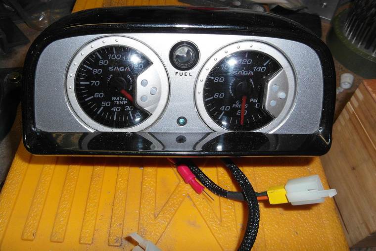
I used to have separate speedo and rev counter but this shows the MkI after I had fitted the Koso. Warning lights are LED.
As the Koso has many of the warning lights this version just had low fuel level and 5th gear lights.
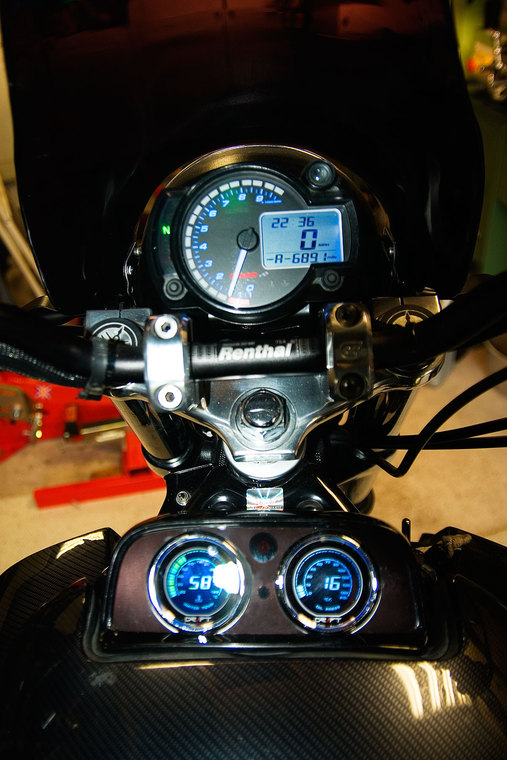
The MkIII was similar to MkII but also has a smoked perspex facia that covers the two warning lights.
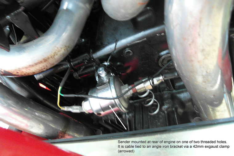
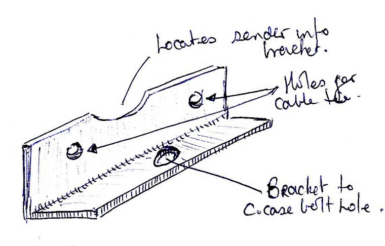
In addition to the faceplate you will also need to fabricate mounting brackets.
I used the same Hitachi type connectors that the OE unit has so that I didn't need to hack the loom about.
Bare in mind that if replacing fuel level and indicator warning lights with LED's you will need to insert ballast resistors as well and also diodes into the indicator lamp if using left and right lights rather than the single OE set up.