Electrical Guru help?!

VMAX  Forum

Help Support VMAX Forum:

This site may earn a commission from merchant affiliate links, including eBay, Amazon, and others.

DigitalArts

Well-Known Member
Joined
Nov 16, 2014
Messages
261
Reaction score
0
Location
College Park, MD
So... Happened to be riding at night today and was lightly bumped in the rear at a red light...

Turns out my tail light only works in neutral and it was definitely like that before the incident.

Could this be related to the removal of the kickstand relay? I only mention it since that also pertains to shifting into gear and both of the relays didn't work (one was bought used but should have worked...)

Also... Bike runs perfect in the cold but holds a 2k+ idle and won't go lower without dying at anything over 70 degrees?
The wiring is crossed up with the neutral switch circuit, would be my best guess.
Carbs. have an overly rich symptom. Check the fuel
enricher linkage for starters?
 
So... Happened to be riding at night today and was lightly bumped in the rear at a red light...

Turns out my tail light only works in neutral and it was definitely like that before the incident.

Could this be related to the removal of the kickstand relay? I only mention it since that also pertains to shifting into gear and both of the relays didn't work (one was bought used but should have worked...)

Also... Bike runs perfect in the cold but holds a 2k+ idle and won't go lower without dying at anything over 70 degrees?

I'd say your tail light is the issue. There's a ground it uses under the seat. If that's bad then it'll find another if it can and it appears that it lies the neutral light/switch ground. Take the rear pillion off and look closely at the black ground wire and connectors.

I agree with Steve, make sure all four choke plungers are closed when choke is OFF.
 
Check out vmaxoutlaw.com. There's an electrical diagram that is separate and that's for 85-89.
 
Attached are 2 schematics for the 85-89 VMax.

VMax 85-89 Wiring Diagram Rev A.pdf shows all the connectors.

VMax 85-89 Simplified Circuit Diagram Rev B.pdf eliminates the connectors which makes the schematic much easier to read.

Electrically, other than the connectors, both schematics are the same.

I have not had an opportunity to verify these.

Gary
 

Attachments

  • VMax 85-89 Wiring Diagram Rev A.pdf
    133.8 KB · Views: 22
  • VMax 85-89 Simplified Circuit Diagram Rev B.pdf
    117.6 KB · Views: 22
Attached are 2 schematics for the 85-89 VMax.

VMax 85-89 Wiring Diagram Rev A.pdf shows all the connectors.

VMax 85-89 Simplified Circuit Diagram Rev B.pdf eliminates the connectors which makes the schematic much easier to read.

Electrically, other than the connectors, both schematics are the same.

I have not had an opportunity to verify these.

Gary

Ho, now that`s the kind of schematic y need for my 1998
do you have it :worthy::worthy::worthy:
 
Ho, now that`s the kind of schematic y need for my 1998
do you have it :worthy::worthy::worthy:

No I don't. I started one, but it is not near completed. Didn't seem to be much interest in them, so I didn't continue with it. They are time consuming to do. The factory schematics are terrible to try to follow.

Gary
 
Attached are 2 schematics for the 85-89 VMax.

VMax 85-89 Wiring Diagram Rev A.pdf shows all the connectors.

VMax 85-89 Simplified Circuit Diagram Rev B.pdf eliminates the connectors which makes the schematic much easier to read.

Electrically, other than the connectors, both schematics are the same.

I have not had an opportunity to verify these.

Gary

Perfect, thank you!

It appears that the yellow line from the Front/Rear brake light switches runs right into the Neutral light, which is around where the grounds start appearing.

Is it possible that the relay has something to do with the tail light going out in gear?
 
No I don't. I started one, but it is not near completed. Didn't seem to be much interest in them, so I didn't continue with it. They are time consuming to do. The factory schematics are terrible to try to follow.

Gary

You did it all :punk: congradulation :punk:

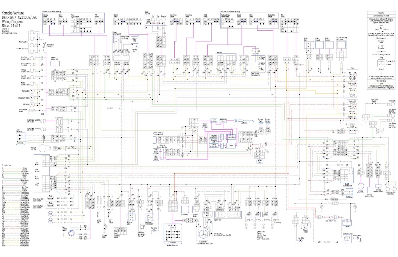
You see, i have it for my 1986 XVZ (attached) and this realy quality compare to the Vmax schematic we found,
Even the diode-block is explained
Verry much easyer to resolve electrical issue as original post here

 
Hey guys! Thanks for all the help, turns out it was only receiving ground from something related to being in Neutral.

I crimped the two wires from it into a wire that grounds to the frame as suggested and now it works perfectly all the time!

As for the blinkers, if there isn't an easy way to make them not blink so fast (easier than 4 resistors?) I might just go back to the older bulbs
You could use a digital flasher, but you'll lose the automatic cancelling feature.
 
The flasher relay is in a combination unit that also contains the starter relay. I don't think it would be a plug and play type swap.

Gary
 
Hey Gary,

When I did this on another bike I own, I simply pulled the two wires for the turn signal flasher out of the plug, and I made a couple of extension wires for the digital flasher. It has been working for me for years. I think the flasher cost me about $15 at an Advance Auto.

I have not done this on my VMax yet, because I am still running regular bulbs in the flashers.

I have also read that one can wire a standard bulb in the circuit (most likely from the flasher indicator wires so it gets both sides) and that can be enough to allow the use of a regular (stock) flasher unit with LEDs; providing enough draw for the circuit. I cannot vouch for that one, though, having never tried it myself. It would be the easiest route to try for the OP, and it should also preserve the self-cancelling feature.
 
i I USED AN ELECTRONIC FLASHER WITH MY LED BLINKERS , BUT I ALSO HAD TO INSTALL A DIODE AT MY TURN SIGNAL INDICATOR BECAUSE THE LED'S WILL LIGHT UP WITH SUCH LOW VOLTAGE , THAT ENOUGH VOLTAGE BLEEDS ACROSS AND THROUGH THE INDICATOR AND CAUSES THE OPPOSITE SIDE TURN SIGNALS TO FLASH AT THE SAME TIME ! .....FIGURES !.. :bang head:..:bang head:..:bang head:..:rofl_200:
 
Back
Top