Stock signal relay and led indicators

VMAX  Forum

Help Support VMAX Forum:

This site may earn a commission from merchant affiliate links, including eBay, Amazon, and others.

satariel666

Well-Known Member
Joined
May 16, 2008
Messages
3,587
Reaction score
8
Location
Where am I? Oh, right here...
Anyone frustrated with led signal lights, forced to buy special led relay and probably still have TURN indicator lights not working...
I have an 97 v-max at my garage with some things to do and owner want to instal set of led signal lights.
I've instaled them and OEM signal relay works with all 4 signals lighting no matter where the switch was set...right or left...
WTF... :ummm:

So evrything is caused by TURN indicator light. Damm Yama used only one light for both directions and as you can see on the diagram.
Think for a minute and the answer "why is this happenig" is quite simple. Led signal consumes less current
and some of that current passes trough gauge cluster TURN light and they all lighting all at once - that small bulb works like a short circut.

That obioulsy not happens with regular bulbs.
Its very hard to get that small double bulb so i done this in mine own way.

First the mighty diagram and some paint changes :)
schemaf.jpg


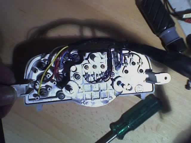
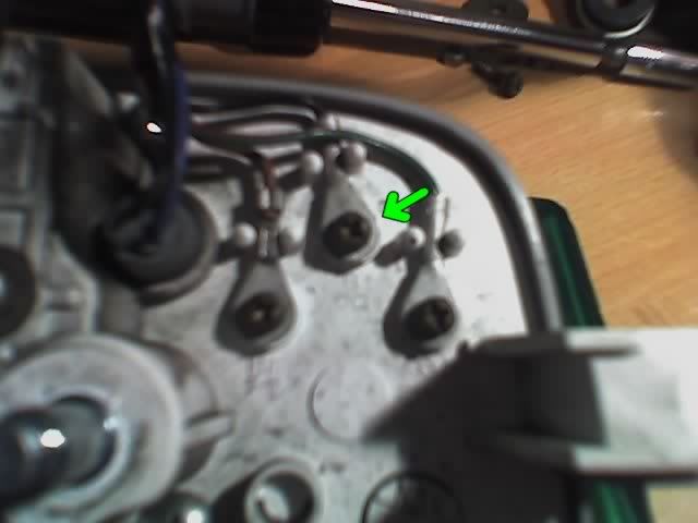
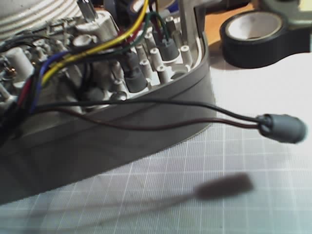
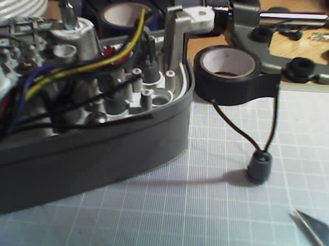
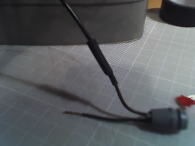
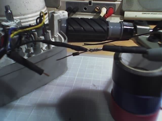
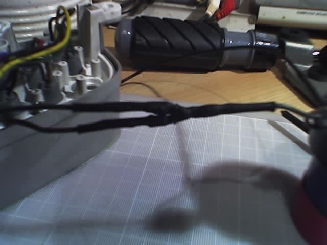
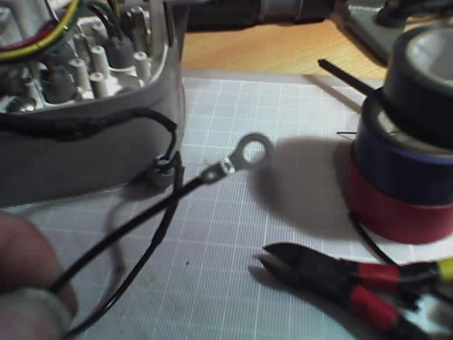
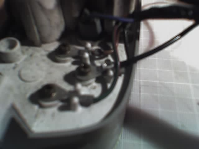
Some photos with work in progress:
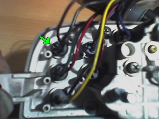
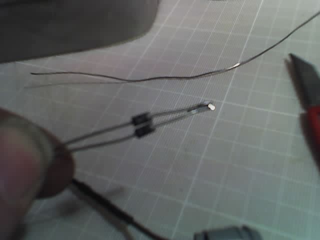
dsc01880.jpg

dsc01885.jpg

And the results:
dsc01890vfv.jpg

dsc01894l.jpg


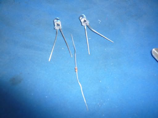
As anyone can see is quite simple and requires 2 led's (i used pair of 120 degree angle, with lightnig voltage 2,2V color orange, standard size 5mm OD) and one 0,125W typical resistor obioulsy to decrease current and prevent led toasting.

At the results i have now TURN signal light at both directions, left and right.
It was not the point but just happend :)
Anyway it works well...:punk:
 
Last edited:
THATS GREAT WORK , MY V-MAX BROTHER ! I WOUND-UP USING A DIODE KIT FROM J&P CYCLES , BUT I LIKE YOURS BETTER !...:punk:
 
Re: Stock signal realy and led indicators

Thanks ;)


I forgot to mention that You need to grind the leds a little couse the stock bulb hole is little to small. Grind them by dremmel for example :)

Anyway ,that 1k resistor was calculated for mine type of diode, that resistor musy be selected experimentally but, typicaly its about 800ohm-2000ohm. Of course its easy to calculate this.
 
Last edited:
Looks awesome! Looks like you may have some good roads to ride on... I see twisties in them there hills... lol (gotta say it with a Southern US accent.)
 
wow, does that electrictal schmatic look like the matrix code to anybody else? im guessing electrical is not my better subject as i am already getting frustrating trying to read these electrical posts!

i bought led blinkers and im getting the crazy shit going on
if i buy non led aftermarket blinkers will the hook up with no issues?

maybe this is my exception to take to the dealership and see how much they will charge to hook them up! if anyone lives near and wants to throw me a bid im in coronado ca. id rather pay you than a stealership.
 
ok, so i went to the local radioshack and it took an hour and a half with customers interrupting but he some what un fucked me.
i bought 2 5mm leds 2.1 volt 20mA 720mcd and 1kohm 1/8 watt resistor
L1020418.jpg


my question is now, i see 2 wires (green and brown) comming off the instrument panel light bulb but i see 3 wires in the picture 666 made. (red,blue,black)
dooes the black wire tie into a ground and the 666 red and blue go to the vmax green brown?
 
Last edited:
Just to make this easier for other guys in the future (I do like the double LED though) I sell a simple diode kit for about $8 that lets the signals work (faster then normal but they will blink).

Sean
 
maybe this is my exception to take to the dealership and see how much they will charge to hook them up! if anyone lives near and wants to throw me a bid im in coronado ca. id rather pay you than a stealership.

:th_pity:
take it to the stealership? what was i thinking? got it working with the resisitor. thanks for the help guys.
 
ok, so i went to the local radioshack and it took an hour and a half with customers interrupting but he some what un fucked me.
i bought 2 5mm leds 2.1 volt 20mA 720mcd and 1kohm 1/8 watt resistor

my question is now, i see 2 wires (green and brown) comming off the instrument panel light bulb but i see 3 wires in the picture 666 made. (red,blue,black)
dooes the black wire tie into a ground and the 666 red and blue go to the vmax green brown?

You got it. that is excatly right. It is then just a matter of working out which wire is left and which is right. But if you describe the wire colours as Choclate and Dark green, I think if you look at the diagram again you should see the relationship between the wires and the switch.
 
Ok. This mod will allow you to use the standard bulb in the centre consol indicator light when using LED indicators without ballast resistors or if you just want to replace the little bulb with an LED unit.
Note: If you see any white squares with red X's inside, just right click on them and select 'Show Picture'


Items needed are:
Soldering Iron & general purpose solder
small cross head screwdriver
some insulated wire (Bike wiring type)
two diodes (1N4001,3,4 or 5 will do)
Some heat shrinkable insulation just big enough to fit over both diodes side by side
wire cutting and stripping tools
crimper and small eyelet crimp (uninsulated for compactness)

Disconnect the centre consol from the bike and remove the instument pod from the outer cover.

26-02-06_1248.jpg


The two areas of interest are arrowed in the next two pics:
Here:
26-02-06_1249.jpg


And here:
26-02-06_1250.jpg


The first is the ground/earth/-v point, and the second is the bulb holder we want to play with.

Pull the bulb holder out and remove the bulb. undo some of the black tape binding the wires to give yourself some room to work.
26-02-06_1256.jpg


Cut the bulb holder off leaving enough wire on both sides of the cuts to do the soldering and for the heat shrink to go over but also to leave enough space to work.
26-02-06_1257.jpg


Solder a 12 inch peice of wire to one of the bulb holder wires (it doesn't matter which but I chose Chocolate). I found the best way is to strip the wires, push the two ends into each other so the strands look like interlocking fingers, then twist to flaten and solder. this makes for a very neat joint that is not much thicker than the wire

26-02-06_1300.jpg


Slip a peice of heatshrink over the wire enough to cover the joint and a bit of the insulation of both wires and shrink down with the soldering iron a bit at a time to avoid burning anything.
26-02-06_1303.jpg


Take the diodes and hold together side by side with the lines that are printed on them at the same end. Bend the leads of the line end so they touch and solder together. Trim the joined and unjoined leads down to about an inch long
26-02-06_1307.jpg


Cut 3 peices of heatshrink. Two long enough to cover each diode and the third to cover the joined leads and the diode bodies. Don't forget to leave enough length to cover some of the wire insulation after joining.
Strip the end of the other bulb holder wire and place the third peice of heatshrink over it (it's best to do it now 'cause you can't once the other end of the diodes are soldered on).
Push the joined end of the Diodes into the strands, twist to flaten and solder together (this is very fiddly). A peice of tape holding the diode bodies together may help prevent the joined leads coming apart. Place the other two peices of heatshrink one over each of the wires from the consol. Strip each wire and solder the free diode leads one to each wire.
26-02-06_1331.jpg


Pull the heatshrink from the consol wires over each diode and shrink down, then pull the heatshrink from the bulb holder wire over both the diodes and shrink down.
26-02-06_1334.jpg


Replace the bulb in the holder. Note: If replaceing with an LED bulb, it only works one way round. So secondary removal of the consol to turn the bulb round, might be required (positive to the diode side).
Push the holder back into its hole in the insument pod and route the wires neatly. The new 12 inch peice of wire can be routed like so:
26-02-06_1341.jpg


Cut the wire so that it will connect to the terminal (arrowed in one of the above pictures) with the crimp attached. Strip the wire enough for the crimp and attach the crimp with the crimper (you could also run some solder into the crimp joint for strenght. But I didn't)
26-02-06_1339.jpg


Attach the eyelet to the terminal using the screw, along with the existing eyelet (under or over depending on which fits best). Tighten the screw making sure that the two eyelets sit as flush with each other as practicable but so as they don't touch any of the other terminals.
26-02-06_1340.jpg


Reverse the disassembly of the instrument pod and replace the consol on your bike and test. Remember the note above on LED bulb units.

Using an LED for the consol bulb will require a resistor (15 ohm 10W) if the original relay is still being used, as it relies on a high current to operate. This needs to be connected in parallel with the bulb holder (one leg of the resistor could be joined with the two diodes to form a tri pod shape before connection to the bulb holder. And the other leg joined to the wire with the eyelet). If you are using an after market relay (to avoid using ballast resistors with LED indicators for example), then the extra resistor is not required.

Cheers

To Admin. This might be better off in the User Mod forum
 
Last edited:
Can anybody help me out with this? I have tried both methods described here, the one using the 2 led's and the resistor and the one using the 2 diodes. Even the diode resistor combination for replacing the factory instrument bulb with an led......nothing has worked. Either they all blink at once, they dont turn on as runing lights or the instrument bulb stays on all the time as well. I used to think I was pretty good with basic electronics until this came along. Am I doing something wrong or is the wiring different in a 94? Please help!
 
Can anybody help me out with this? I have tried both methods described here, the one using the 2 led's and the resistor and the one using the 2 diodes. Even the diode resistor combination for replacing the factory instrument bulb with an led......nothing has worked. Either they all blink at once, they dont turn on as runing lights or the instrument bulb stays on all the time as well. I used to think I was pretty good with basic electronics until this came along. Am I doing something wrong or is the wiring different in a 94? Please help!

I have done this with 97 for a first time and as far I know there was no changes form 91 to the far end with electrics.

I think you may need to post some more details, pics maybe so we can get better chances to help!
 
Sorry, didn't take any pic. Got to frustrated and put everything back together minus the instrument cluster bulb. With the bulb out of the instrument cluster the LED directionals work fine. With the stock bulb "in" I get 4 way flashers and the instrument cluster bulb does not light up at all. I tried the 2 LED and resistor method but everytime I ground the circuit the LED's will light up partially and stay lit up. Then I tried the 2 diode method and replaced the stock instrument cluter buld with a single LED and tied in the resistor as described and it still didn't work. I tried a couple of different resistor values and either the LED would stay lit all the time or it wouldn't light up at all.

For the diode method I was using 2 1N4001's as mentioned above along with a 10 watt 10 ohm resistor and a 2.1 volt 20mA 720mcd LED

For the 2 LED method I was using 2 5mm, 2.1 volt 20mA 720mcd LED's and 1k ohm 1/8 watt resistor

Hopefully this will better help someone figure out what I am doing wrong. Do I have the wrong value on some of the parts maybe?

Don't use any resistors with the Diodes at the instrument cluster amber light, combine the diodes ends with the silver band together & solder them to the brown wire going to the stock indicator bulb, the green wire to the bulb should be grounded to the frame.
 

Attachments

  • diodes.jpg
    diodes.jpg
    18 KB · Views: 67
  • Diode fix (256 x 192).jpg
    Diode fix (256 x 192).jpg
    12 KB · Views: 59

Latest posts

Back
Top