naughtyG
Well-Known Member
yo Pat that's just mean.. LOL


There're non inductive WIRE resistors, I have VISHAY gold, WIRE resistors andFirst, sorry about this long winded post . . .
As an electrical engineer I'll say that the resistor need not be non-inductive so just select them on their resistance and body style. The gold metal power resistors that many are using are "wire wound" and these are inductive. The caddock brand resistors are non-inductive because they are a "thick film" type resistor. The ignition coil and cops are inductive by nature because they are "wire wound" coils so buy either type.
Another thing, the original coils are around 2.75 ohms. If your cops + resistor are less then more current flow and greater heat is generated in the ignition module. This is why some Dyna modules have failed without resistors. Based on what I've read here on the forum the Yamaha modules seem to tolerate the higher current a bit better because I haven't heard of a factory ignition module dying with cops added. Has anyone else?
A single resistor, properly selected and placed in series with the red/white wire feeding the coils should work. This would keep the cops harness clean and perhaps give us more options of how to mount the resistor out of sight.
I'm waiting on my Denso cops to arrive and I'll gladly be the guinea pig with this single resistor approach. All I need are my harnesses (hint, hint. Gannon, do you have any left?) and I'll get started. You don't want to fry the ignition module or the cops resistor or the cops itself on a hot day or a long ride. The only way to pick the right resistor is with careful measurements taken on the bike while it's running. Too low a resistance and the cops may arc to the chassis due to over voltage (been reported on this forum), and have a shorter life. Too high a resistance and it will produce a weak spark. Because there are different cops with different internal resistances there will likely be different external resistors required on a case-by-case basis. This doesn't lend itself to a one-size-fits-all cop harness solution.
One final thought, the wattage of the resistors that is printed on the case is not what the resistor can handle unless its securely attached to a proper heat sink. Without a heat sink, or even worse, insulated in electrical tape or other wrapping, the actual wattage that the resistor can safely handle is reduced considerably.
There're non inductive WIRE resistors, I have VISHAY gold, WIRE resistors and
they're non inductive. I even check that with proffesional LCR meter.
I agree with You, those could be non inductive or inductive as It DC suply and we dont have reactance there.
However, current flowing trouh ignition coil is not constant as the CDI sending
impulses at diffret frequency. About 2 per one rev. as it wasted spark.
Think about that this may work as AC suply and by then, then higher inductance then higher current.
More then that, then higher revs then HIGHER CURRENT.
Put a 7,5A fuse to the ignition section and observe.
When engine revs up to about 6000 rpms the 7,5 A fuse will hold.
By passing 6000 rpms the 7,5 fuse will fry...
Thats why I do recommend non inductive resistors
No need for You to verify that, I already done this.
1 Ohm, 50W, gold, non inductive resistors works fine with Denso and Mitsubishi COP's.
But 50W is to high as mine are not even warm, anything beteween 25-30W will work fine.
To my knowledge Yamaha called it a 'TCI' - transistor-controlled ignition.
Yes, Its all good.All I meant to say is that you can use either as it doesn't matter much at all and most wirewounds are inductive. The ignition circuit is designed to work with highly inductive elements such as our ignition coils so a little more inductance won't hurt. Even though the circuit is powered by DC it is "switched DC" or "pulsed DC". The switching, in this case, is what would cause us to consider the effects of inductive components. When revving the engine the duty cycle of the ignition/coil/plug is increased therefore the average current is increased and this is why the lower rated fuse will blow. A fuse is a thermal device and it is generally heated by average current over time.
Is the ignition module truly a CDI or is it just an inductive ignition? It'll make a big difference in the final solution for the search for the best cop for our needs. CDI or inductive ignition call for very different cops.
Nope, Its 4 cyl wasted so 2 coils fire at once, more less.Thanks! It's not likely a CDI ignition because inductive ignitions are by far the most common. I'll soon be scoping my ignition to see the actual duty cycle that is used by the stock ignition box and comparing that to what is considered safe for cops. The result should indicate the correct resistor to use to get good performance from the cops without shortening the life of the cops or the oem ignition box.
One more thing, it is my understanding that only one coil is fired at a time on the Max. Can anyone confirm this? In any case I'll be verifying this when I scope things out.
You may go without any hestation with 1 Ohm 30W (I still recommend non inductice) one resistor per COP, on either positive or negatice wire.Satariel and Bon-86 you both have a very good imput on this subject. I can see the potential problems with this conversion if we don't address them. We obiously want a hotter burn from our plugs without having premature ignition failure! I am guessing to make these harnesses the most simple we should stick with one COP manufacturer. So we can set these harnesses up so we get the best possible burn of our fuel.
Gannon
 unk:
unk:Hey Gannon,
I did my cop mod about 4000 miles ago. Bike runs great. I did blow up a Dyna when I first did the mod. Then had an issue when using Mitsubishi cops. Now I run the Denso's and it's been a pleasure ever since.
I want a set of your wires. Tell me if you kept the polarity correct though. I made my own harness using parts from the cop's original harness and parts from the original coils. I made sure the polarity was kept as the factory intended.
If you're keeping the polarity correct, I want to get a set.
You take PayPal?
Vinnie
My previous post isn't meant to put the kabash on COP's. But rather it's meant to stake out a starting place in my mind. As far as I'm concerned I'm just cranking up my problem solving mode.
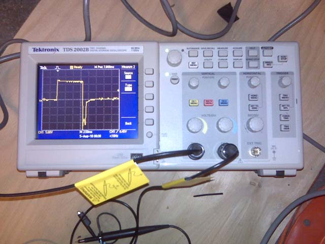
This is what an OEM ignition waveform looks like on an oscilloscope:
The scope tells me the following:
The OEM coil is charged for 8 milliseconds (0.008 seconds) with 12 volts. At the very end of the 8 millisecond period the plug is fired and the spark lasts for around 1 millisecond. The peak reverse voltage (PRV or PIV)) seen by the OEM TCI module is around -15 to -20 volts.
When I get my loaner cops I'll again do this test while using various resistors and determine what resistor best reproduces the same load on the OEM TCI module as we don't want to stress it out. I'll also adjust the resistor to limit the energy to the cop to its normal maximums. I have no idea (other than in my previous post) as to how this will come out.
One last thought: There are likely some efficiency losses when using a separate ignition coil and spark plug wire but not a lot. Manufacturers went to using cops because it's cheaper and easier for them. Then, given that the traditional coil/plug setup is about the same efficiency as the cop solution then the one difference glaring difference is the size of the coils and their close proximity to engine heat. The cops is a lot smaller and therefore will not be able to transfer as much energy as a large external coil; and, because of the heat, it will not be able to be driven as hard as an external coil.
That said, I'm hoping for a good surprise when I begin my testing with the cops. I hope that I'm underestimating their performance. I want them to work! We know that others are using them and have quite a few miles on them at this point. That is a great sign that either the calculations are pessimistic or that the OEM TCI module is more robust than expected.
If you ask me, the answer is yes, but the question is which resistor?Are you guys saying, that even with stock ignitor boxes (TCI)
that we should a resistor in series with the denso cops ?????
<<Dave>>
Nice but You forgot about voltage drop...I have only a minute to post this but I want to get it out here to let others see what I'm thinking:
OEM coils setup
Supply voltage: 12 volts
Charging duration: 8 ms
Coil Resistance: 2.75 ohms nominal
Current @ 12 volts: 4.36 amps nominal
Energy dissipated per cycle: ((12 * 12) / 2.75) * .008 = 0.42 watt-seconds (Joules)
Peak reverse voltage during discharge: 15-20 volts @ 1ms
Typical COP design criteria:
Supply voltage: 12 volts
Charge duration: 2.5 milliseconds (I have read that 3.5-4.5 milliseconds shortens their life from heat buildup.)
Coil resistance: 1.5 ohms nominal
Current @ 12 volts: 8.0 amps
Energy dissipated per cycle: ((12 * 12) / 1.5) * .0025 = 0.24 watt-seconds (Joules)
(3.5-4.5 milliseconds translates to .34-.43 watt-seconds)
Hybrid Design – OEM TCI box with COP @ 1.5 ohms:
Supply voltage: 12 volts
Charging duration: 8 ms
Coil resistance: 1.5 ohms nominal
Current @ 12 volts: 8.0 amps
We must control the current with added resistance so solving for X:
(Energy dissipated per cycle: ((12 * 12) / X) * .008 = 0.24 watt-seconds (Joules)
X = 4.8 ohms. Since the cops is 1.5 ohms the resistor must be 3.3 ohms to protect the cop.
A 1 ohm resistor and a 1.5 ohm COP transfers 0.46 watt-seconds of energy which exceeds any limits that I have seen.
Enter your email address to join: