LED turn signals wont blink

VMAX  Forum

Help Support VMAX Forum:

This site may earn a commission from merchant affiliate links, including eBay, Amazon, and others.

oz1961

Well-Known Member
Joined
Aug 17, 2013
Messages
142
Reaction score
11
Location
Japan
I just changed my ’85 original turn signals on my Vmax to LED’s
The problem is that they don’t blink
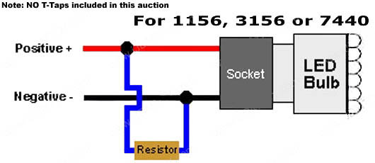
I read that the problem is that I now need to fit a resistor in each turn signal side

Has anyone else had this problem?
If yes how did you fix it and what resistor/s did you use
Thanks
 
They should blink fast... The relay is controlled by power in the circuit, the higher the power rating the slower it blinks so as LEDs are pretty low power the blinkers tend to blink at a faster rate. What you need to do as Steve suggested is to add a power resistor to mimic the power of the bulb. The resistance should be around 5 Ohm as that will control the current and brightness of LEDs. The power of the resistors should be around the same as the bulbs. Blinkers are normally 27w so around 54w per bike side. Due space restrictions i'd recommend using what Steve suggested so a 50w resistor per side (remember that the higher the wattage the higher the heat dissipation it needs - fix it against a metal surface on frame). Or you can go with one resistor per blinker like the pic below. That one was on my bike before i went with the newer style aluminium encased ones.

Here below is an example of a resistor for a single blinker

28022011329.jpg


Heres a simplified way of connecting the resistor in parallel to the circuit. If using a 50w resistor you only need one per side (2 blinkers), i recommend installing them under the rear seat or around for neatness and concealed wiring type of thing.

02.jpg


If you don't mind loosing the self cancelling feature of the blinkers you can get a cheap digital blinker relay that doesn't need resistors to make the stock relay work as supposed.
 
Last edited:
Hi and thanks for everyones comments! Its been a great help to me.
Just a few questions I have to qualify the advice.

With two LED lights fitted, my signals still flash but faster, with three or four fitted none flash

question
If I just put a 50w 8 ohm resistor in each side, will it be enough?
or should I put 4 x 25 watt x 8 ohm resistors?

Question

One comment was to install an LED blinker unit.

this sounds easier
has anyone had any problems with this simple fix?
or is the idea situation resistors and new unit?

Thanks for your comments
 
Like the Ebay link I showed it claims 1 x 50w x 6 ohm load resistor per bulb.

Pretty sure just installing a LED blinker is going to make your self cancelling feature of the OEM set-up redundant.
 
Thanks, I dont think I use the self cancelling blinker but I actually may use it much more than I have thought

I just ordered the resistors
Ill let you know what happens when they arrive

Thanks
 
As soon as the resistors have arrived and I have fitted them I will post some pictures
 
I installed the CBR taillight mod then replaced the front two bulbs with LED bulbs. It did flash faster than I liked so I purchased the cutom dynamics LED flasher, installed it and NO issues. The flash rate is perfect and since my self canceling never worked I don't miss it.


David Justiss
USAF First Sergeant
554 RED HORSE Sq, Guam
 
I wanted to write and let everyone know about my LED lights and lead resistors.
I ordered two resistors of the net.

I fitted them both at the rear and everything worked fine

The most difficult thing for me was finding a metal base to mount them on.
The resistors came with a warning that they get extremely hot and need to be fitted to a metal base to help with cooling

It’s difficult to find anywhere to mount them
Finally I decided to fit the between the bike frame and the alloy rear bar

They are able to stay cool and made fitting and wiring easy

After fitting everything was working fine
The turn signals work great and the auto switch off for the turns signals work as normal

Thanks for everyone’s help

I hope the pictures help others in what to do or not to do
 

Attachments

  • Bike left fitted.jpg
    Bike left fitted.jpg
    33.9 KB · Views: 63
  • Bike right side fitted.jpg
    Bike right side fitted.jpg
    45.3 KB · Views: 61
  • Bike top fitted.jpg
    Bike top fitted.jpg
    43 KB · Views: 68
  • Bike lights fitted.jpg
    Bike lights fitted.jpg
    33.1 KB · Views: 61
On my Gen 1 I bought a flasher relay. they all flashed like hazaards. ended up having to take out the bulb in the turn signal indicator on the display. now they all work great. on My GEN 2 I used resistors for the two rear LED signals and they work fine. have not done the fron two yet as I'm still looking for a way to mount them that I like. If you do go with resistors you definitely want to mount them to a metal surface and get the aluminum ones that have heat sink top dissapitate the heat.
 
Why wouldn't some itty bitty resistors such as these work for turn signal stabilization in our gen 1 Maxes? It seems like they'd be far easier to hide.
resistors.jpg
I don't have LEDs in my 85, but do have them installed on my 09, and these tiny resistors are what is in-line on it. Tiny things are soldered right in the power wire, and hidden in heat shrink wrap, then enclosed in black tape to hide so well, you can't tell they are there.
 
Don't worry much about overheating them as the self cancelling feature will put them to stop and its not constant load its intermittent. They get warm. Try it out and see if im right. The self cancelling feature is related to distance driven and time elapsed as well. It cancels after 10 seconds or 150 meters whichever is higher but only if the bike is moving. If you sit in traffic it won't self cancel.
 
Why wouldn't some itty bitty resistors such as these work for turn signal stabilization in our gen 1 Maxes? It seems like they'd be far easier to hide.
View attachment 41658
I don't have LEDs in my 85, but do have them installed on my 09, and these tiny resistors are what is in-line on it. Tiny things are soldered right in the power wire, and hidden in heat shrink wrap, then enclosed in black tape to hide so well, you can't tell they are there.

In this case you are using POWER resistors in order to mimic the power of the bulbs and deceive the relay and make it think that there's a bulb there when in fact there's a resistor with the same power (give or take). This relay works depending on circuit load and when you add LEDs the total power will decrease thus making the relay flash faster. Its the same thing when you burn a bulb on a car an the other blinkers start to blink faster because of the decrease in load on the circuit.

The resistor setup you are talking about are to make LEDs that have nominal voltages of about 3 volts to work with 12 volts from the battery you can either add individual resistors or make series of 4 LEDs to account for the 12 volts as the voltage will be divided by the number of LEDs if they are in series.
 
The hardest thing for me was fitting them to my Gen 1 max. Maybe others found a better place but it was a struggle for me to find anywhere that I thought wa safe and wouldnt melt anything if they got to hot

I am happy where I put them and happy how they are working, but if a smaller in line resistor worked it would make things a lot easier
 
On my 09 the front LED's have both running light and turn signal feature......but somewhat odd internal wiring on their circuit boards. Each has either 12 or 15 LED's in them (don't remember which). Only the center 3 LED's light up as full time running lights. All 12 or 15 light up & begin flashing on whichever side when the turn signal lever is hit.

I had to add a diode to the running light wire on each side of my front signals so that the turn signal application would not feed back through the running light wire and illuminate both sides when I hit a left or right blinker. The LED boards in my front signals are made in such a way that I had to do this to make them work correctly. Also have to have a 3.3k ohm resistor in each of the running light wires to prevent all 12 LED's from lighting at once with only the running light wire attached and key on.

Cost me the better half of a day, and some quality Google time when I had to switch them out. I wasn't prepared for the difference between internal wiring when I switched out an old one that had stopped working. The old LED's simply had the small resistor in-line to work properly, and didn't require that diode to separate the features from interfering with each other. Zero instructions with the replacement LED's I had bought.

The LED specific flasher was already installed for correct flasher speed when I bought the bike, and continued to work correctly with the new front LED's installed once I figured out I needed the diodes.
 

Latest posts

Back
Top